Select measurement type to begin. Not all functions and features are selectable from the meter.
Best Practice: Convert measured DVOM reading to service information value.
Numeric Reading
Type
Convert
to
Result
Clear values
Select measurement type to begin. Not all functions and features are selectable from the meter.
DVOM+ is a performance support tool primarily designed for those diagnosing and repairing complex electrical systems using high-end digital multimeters such as those offered by the Fluke Corporation. The DVOM+ app focuses on voltage, current, and resistance measurements that will be typically encountered by today's automotive, transit, and medium/heavy duty technicians.
DVOM+ for the iPhone is a no frills performance support app that will allow you to quickly and accurately convert your measured DVOM/DMM readings to your specified service information value for those times when your unit of measurements (multiplier) differ. Also available, are quick tips such as 'when to use' and 'how to make' measurements for voltage, current, and resistance.
DVOM+ for iPad is an interactive version of the iPhone app that includes brief descriptions of all the functions and features of the Fluke 88V and 87V Automotive Multimeter as well as interactive knowledge activities to test your knowledge. Future releases of DVOM+ for iPad will include interactive quick reference guides, access to many of the more popular DVOM's/DMM's in use today, basic circuits Breadboard simulation, and basic networking. In the meantime, we hope that you find the DVOM+ app useful in your workplace.
OHM'S LAW
Why do technicians need to know about Ohm's Law and how could it help technicians diagnose vehicles?
It is important, when diagnosing a vehicle, to understand the relationship between volts, current, and resistance.
Let's examine the relationship between resistance and current:
High Resistance = Low Current
Low Resistance = High Current
Resistance is one of the most common problems within an electrical circuit. High resistance results in low current flow. When unwanted resistance is found in a circuit, there will not be enough current to perform a needed action or provide a proper signal.
As resistance increases in a circuit, the location where the resistance occurs will drop voltage.
Example:
There is corrosion in a connector causing resistance. Instead of the connector reading 0.01v, it might read 2.0v. Remember, all voltage must be used in the circuit, if 2.0v is being dropped at the connector, that that would be 2.0v less to the actuator which would read 10.0v instead of 12.0v. This principle applies to any location within a circuit.
A typical switch or relay should have very low resistance across the contacts, which means there should be very little voltage drop. However, if the relay contacts were corroded, too much voltage would be dropped at the relay and less voltage would get to the component. If the contacts had 1000 Ohms of resistance for example, then we divide 12 (Volts) / 1000 (Ohms) = 0.012 Amps. It is possible with high resistance, that a motor would not turn or a light would be dim (or not on at all).
Each and every part of a circuit will have additional resistances whereby the sum of all of the resistances equals the total resistance in a series circuit. Wherever there is resistance, voltage will drop.
DEFINITIONS
Alternating Current (AC) - Electric charge flow periodically reverses direction - positive to negative and negative to positive.
Amperage or Current - Is the flow of electrons through a wire or conductor. Current is measured in (A) amperes or amps.
Back-Probe (Back-Probing) - There are many times when circuit measurements need to be made while a connector is still attached. This technique is called back-probing. The back-probed pins are placed between the connector and wire eliminating the need to puncture the insulation.
Direct Current (DC) - Electric charge flows in only in one direction - positive to negative.
Diodes - Allow current to flow in one direction, similar to a one-way check valve.
Duty Cycle - Is the ratio of time a load or circuit is on compared to the time the load or circuit is off.
DVOM - Digital Volt Ohm Meter is a measurement tool that can be used to diagnose and troubleshoot vehicle electrical systems.
Frequency - Is the number of times per second an event occurs.
High Impedance - Means that the internal resistance of the DVOM is enough to prevent excessive current draw from the electrical circuit being tested. Most DVOMs including the Fluke Model 88 V Automotive Multimeter have a minimum of 10 megohms of resistance. High impedance DVOMs reduce the amount of current flowing through the meter when it is being used for voltage measurements. This reduction in current flow provides for more accurate voltage measurements as the load on the circuit is not changed.
Ohms or Resistance - Is any force that opposes the movement of electrons. Resistance is measured in ohms.
Ohm's Law - The current in a circuit is directly proportional to the voltage and inversely proportional to the resistance.
Parallel Circuits - Parallel circuits are created when each load has its own path for current flow. The paths for current flow are often called branches or legs.
Series Circuit - A series circuit is created when all loads are connected with only one path to ground for current flow.
Series-Parallel Circuits - Series-parallel circuits are created when you combine a series circuit with parallel circuits. Each segment of the circuit must be evaluated separately and those rules applied to that portion of the circuit.
Short-to-Ground - A Short-to-Ground can affect components and circuits differently depending on how the circuit is controlled.
Voltage - Is the difference in electrical potential between two points in a circuit (PRESSURE). It's the push or pressure that moves current through a circuit and is measured in (V) volts. Electromotive force, called EMF, is measured in volts and refers to the voltage produced by the battery.
Watts or Power - Is the amount of current multiplied by voltage measured in wattage or watts (W).
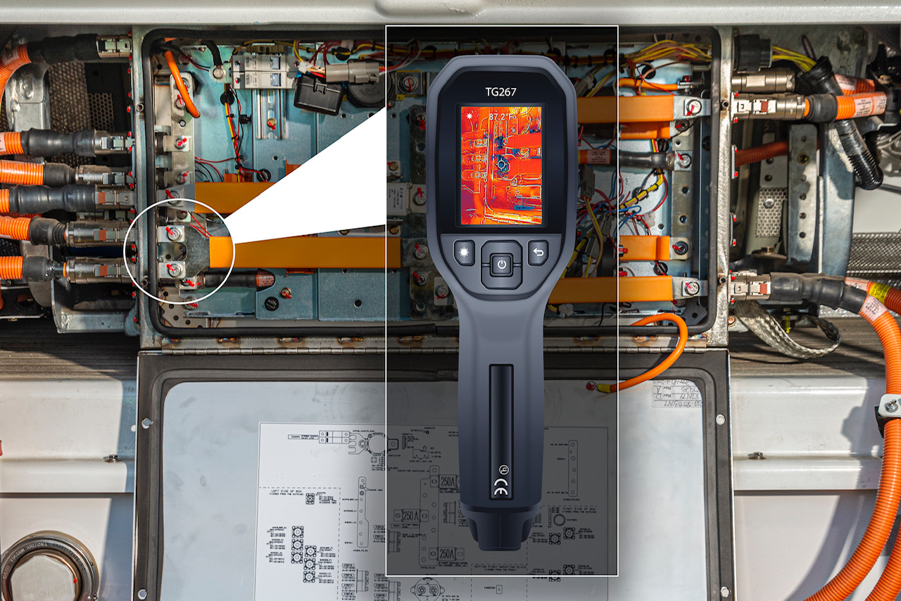
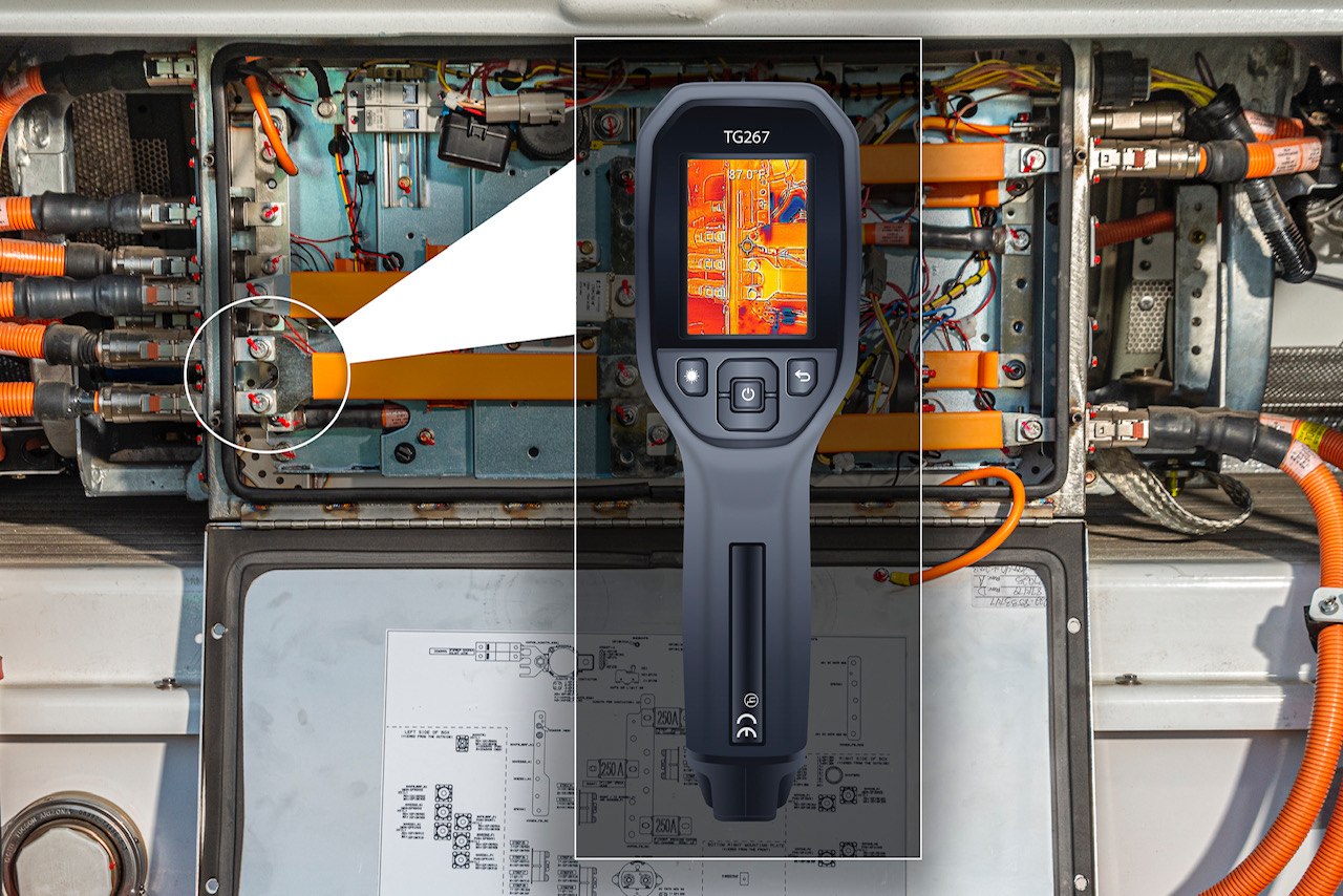
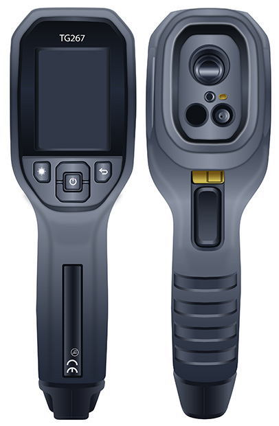
Electrical Hotspots
A thermal camera detects infrared energy or heat and overlays a specialized thermal image on a real-world image. When current flows through an electric circuit, part of the electrical energy is converted into heat energy. An abnormal heat signature means there is current flow present; Excess heat caused by increased resistance. This could be caused by:
Loose Connections
LDamaged Components or Contactors
LExcessive Current Flow from Improper De-Energization
Using a thermal camera is another method of "Test Before Touch" before a technician makes contact with high voltage bus bars or contactors during the "dead" part of a live-dead-live test.
The following examples compare and contrast a High Voltage Fusebox with the system energized and de-energized.
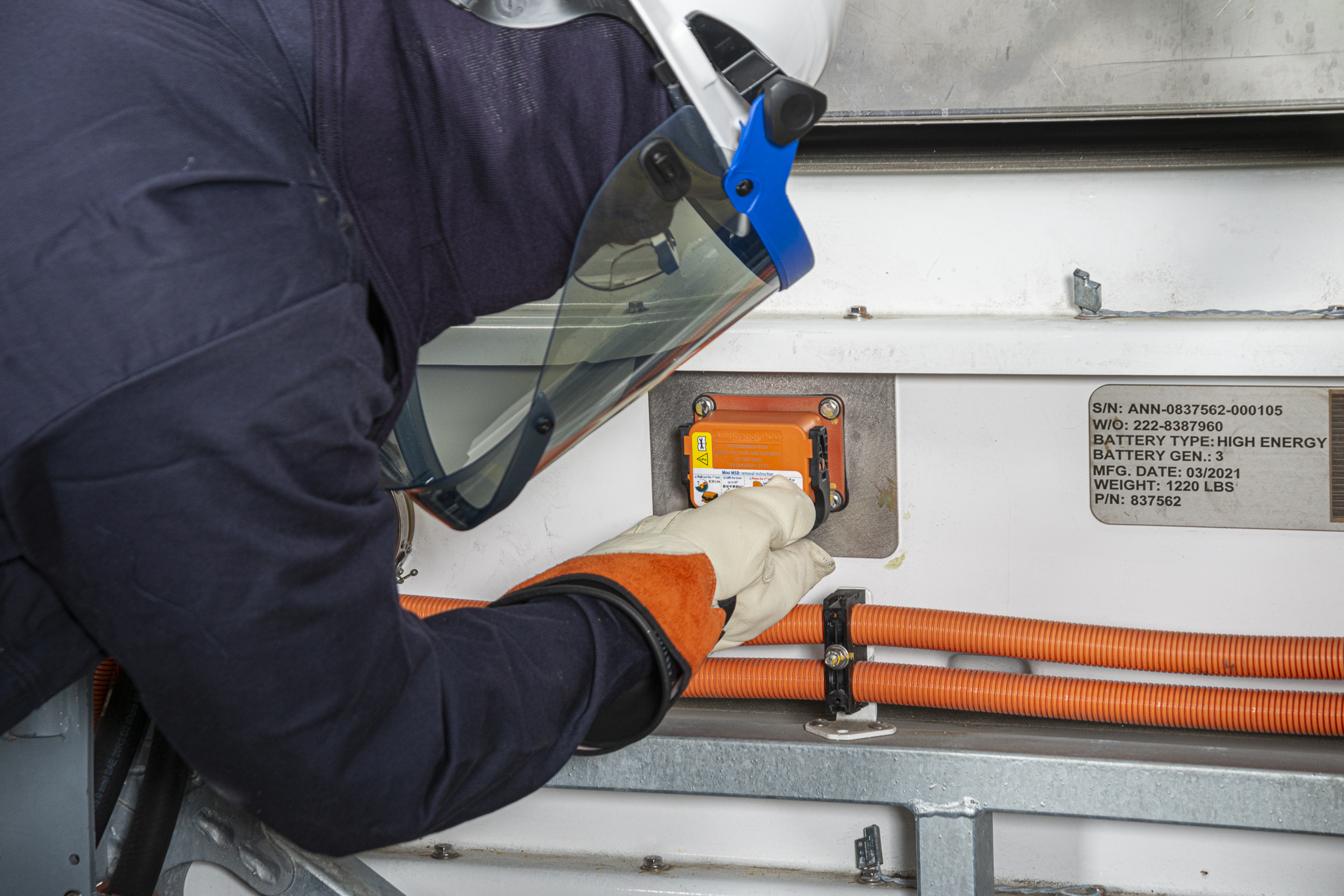
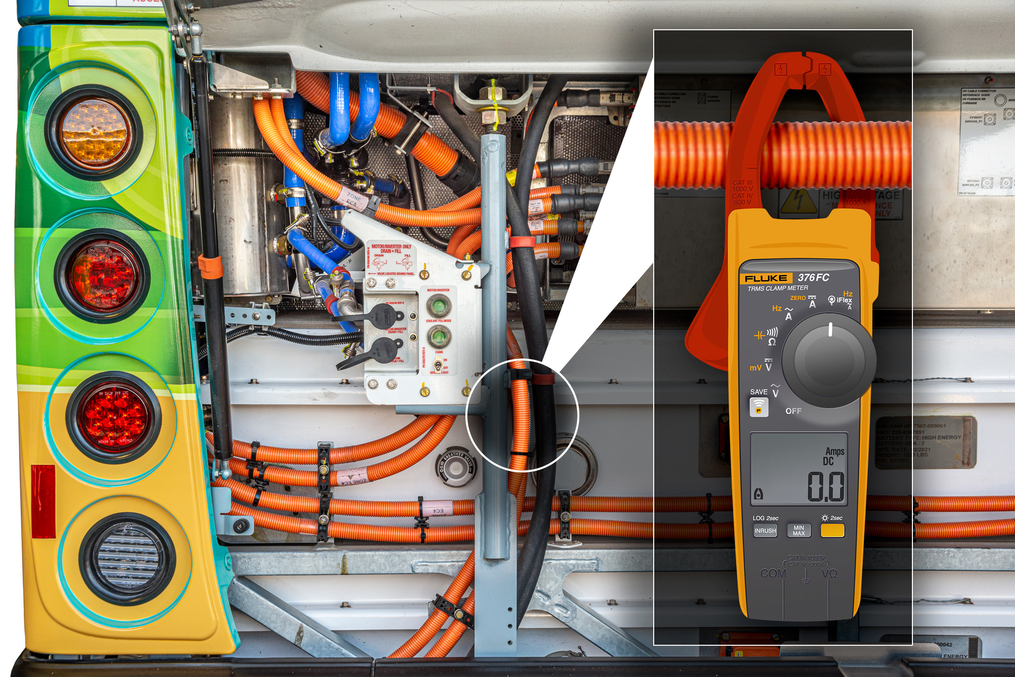
MSD Removal
WARNING: NEVER remove the ESS Manual Service Disconnect (MSD) plug(s) while current is flowing. The High Voltage may create a long enough ionized gas path, during circuit interruption, to bridge the contacts of the MSD receptacle base and MSD plug fusable contacts and therefore continue the path of current flow through the air. This can cause an arc flash. The ionized gas from an arc flash is very hot and can cause:
Burns
Fire
Arc Blast
Electrical Shock
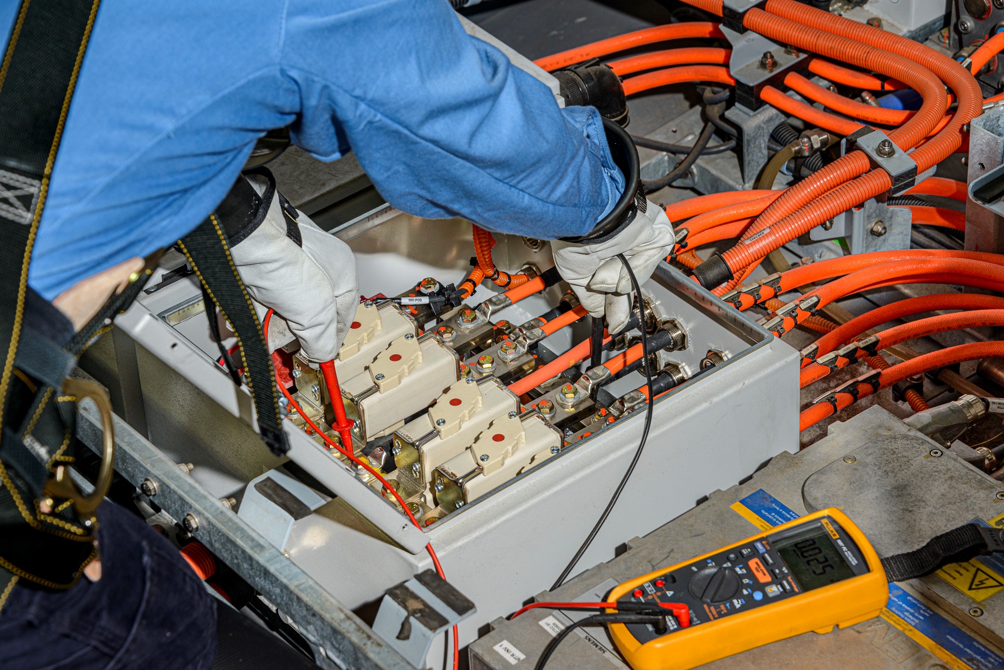
Using a clamp-on current probe and DVOM or standalone inductive amp clamp, ensure that there is no current flowing in the High Voltage orange cables cables connecting to the ESS enclosure.
WARNING: ALWAYS follow and understand manufacturer specific procedures for removal and installation of ESS Manual Service Disconnect (MSD) plugs for the system you are diagnosing and servicing. Always know how to verify the absence of high voltage and create an electrically safe work environment.
LIVE-DEAD-LIVE
When working with high voltage systems and components, the Zero Voltage Verification (ZVV) procedure is performed to verify the absence of voltage in de-energized systems and components. Voltage greater than 50 volts is high voltage.
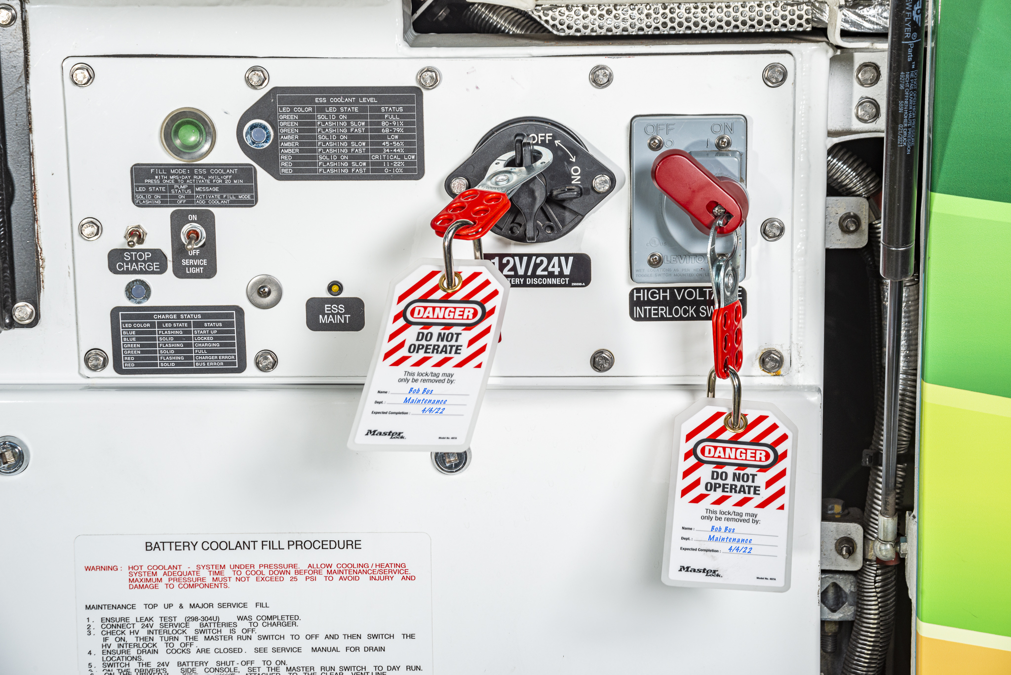
To create and ensure an electrically safe working environment, a trained technician will test for the absence of voltage after performing a lockout/tagout (LOTO) of the system or component.
WARNING: Never attempt to verify the absence of high voltage using any method or procedure that is not first approved and authorized by your employer and you are trained to do so.
REMINDER: All LOTO and ZVV procedures have SOPs and are performed by a Qualified Person.
A live-dead-live test will determine whether voltage is still present in the system or tested component when compared with a known live connection. Testing the DVOM before and after the actual measurement ensures that the DVOM is operating correctly.
WARNING: The technician must wear appropriate High Voltage Personal Protective Equipment (HVPPE) while performing a live-dead-live test on high voltage systems and components.
WARNING: The technician must use a properly rated Category III/IV DVOM while performing a live-dead-live test on high voltage systems and components.
WARNING: To de-energize a high voltage system or component, always follow manufacturer's correct procedures and safety precautions needed to safely work. The following steps are for illustrative training purposes only.
WARNING: Always verify ground connection before performing phase-to-ground measurements.
Step 1: Perform system LOTO per your shop's established procedures.
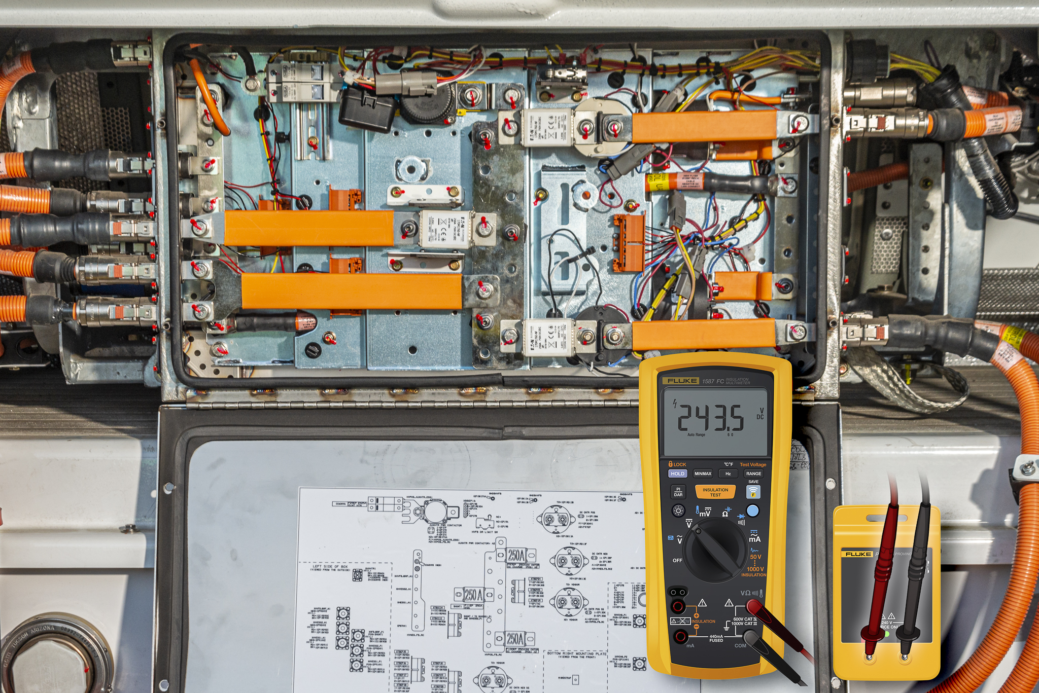
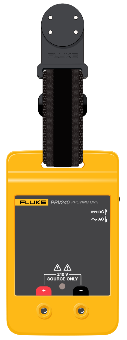
Step 2: Using a Fluke Proving Unit, test the DVOM to ensure it is working correctly.
WARNING: Verify zero or near zero voltage for each phase-to-phase measurement. Meter may read dissipating capacitance before reading zero volts or near zero volts.
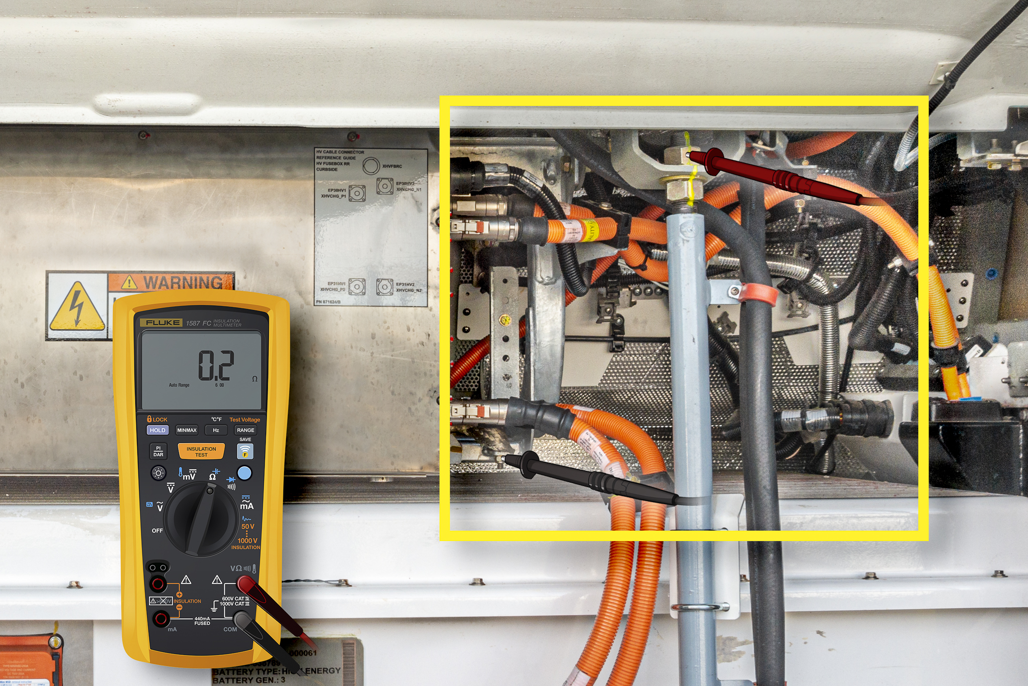
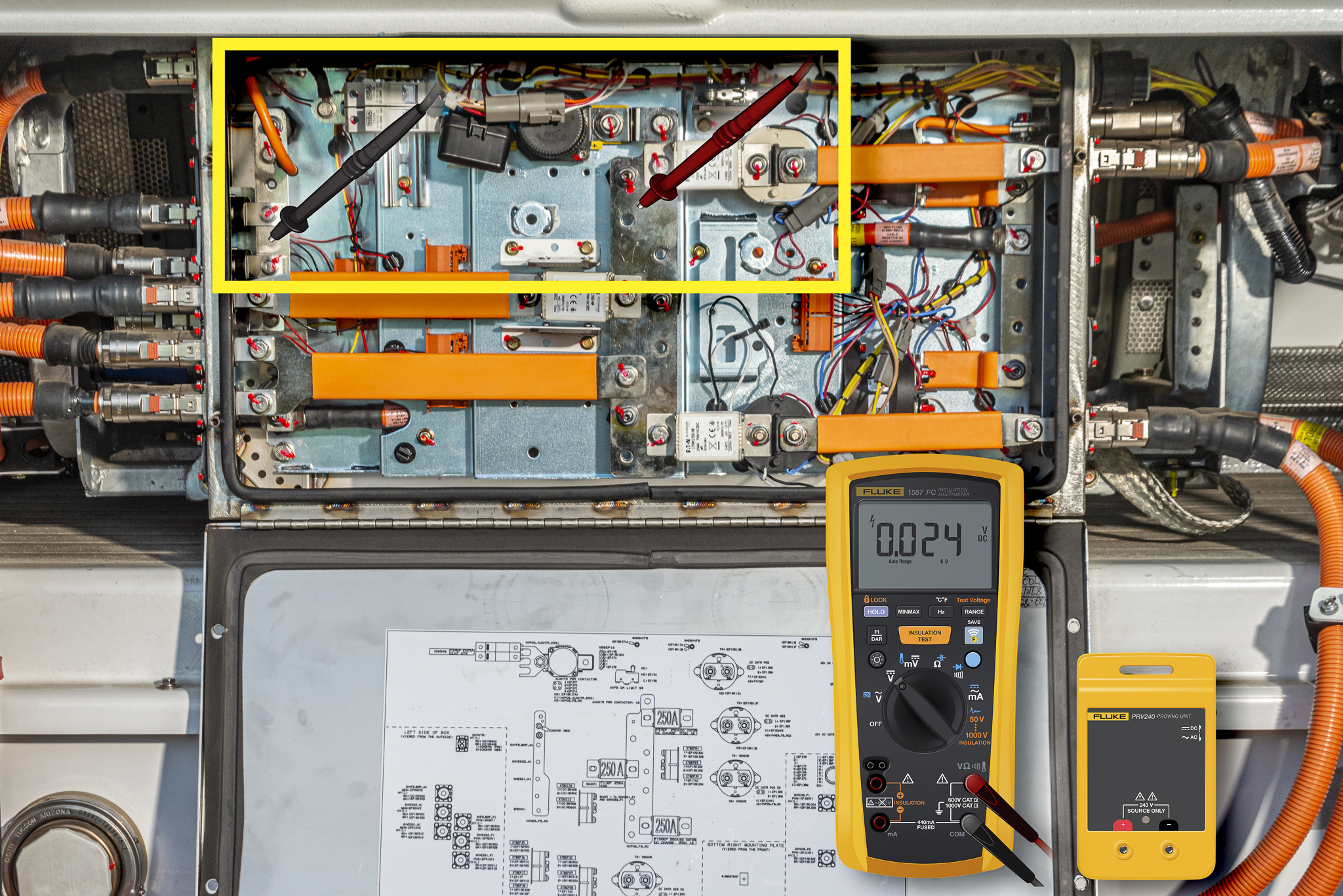
Step 3: Measure from the High Voltage Positive Bus Bar to the High Voltage Negative Bus Bar.
WARNING: Verify zero or near zero voltage for each phase-to-ground measurement.
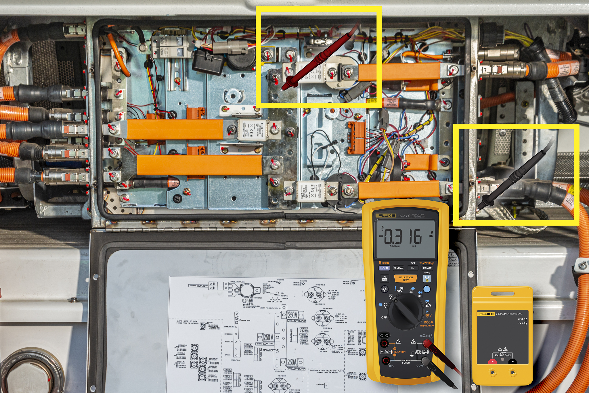
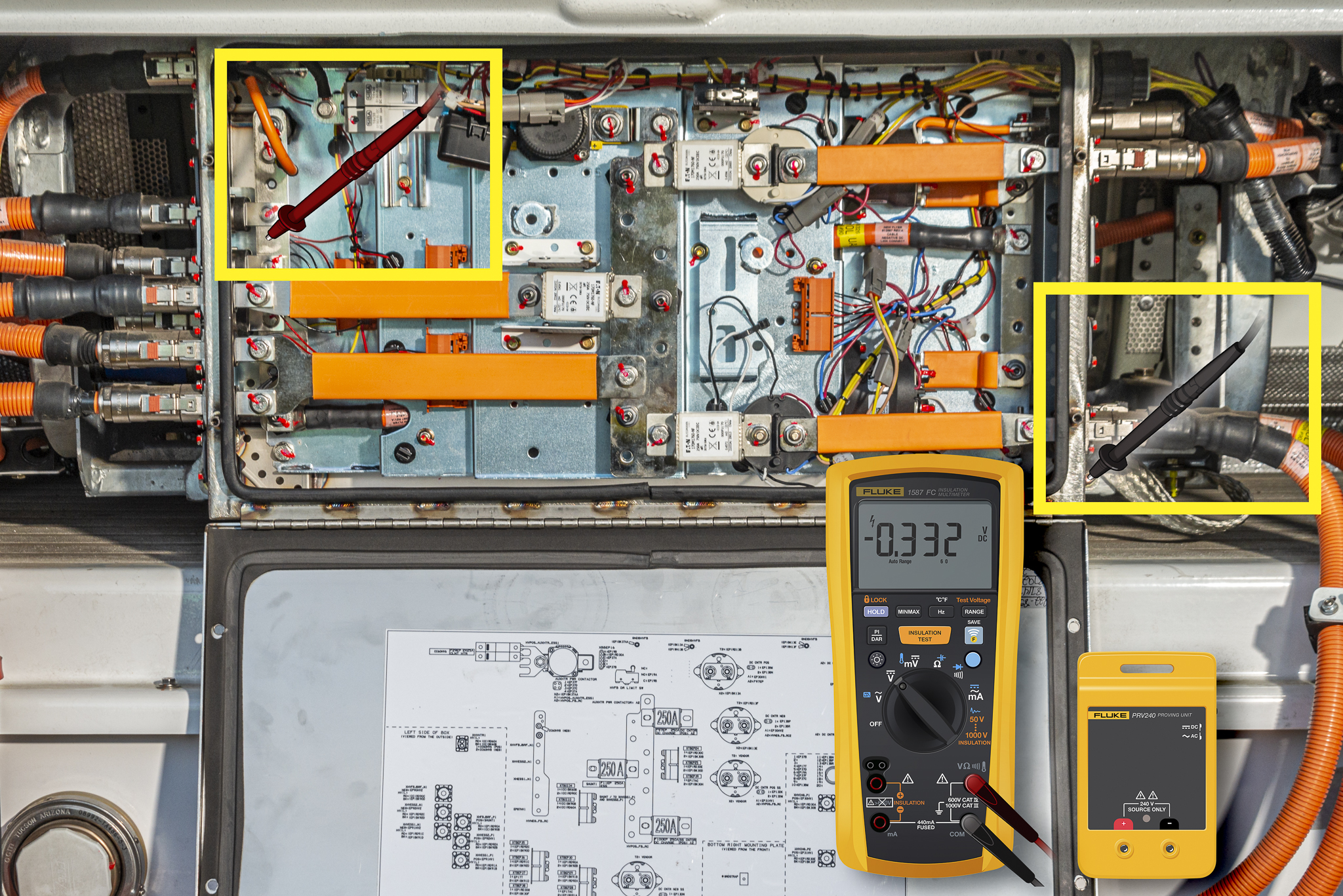
Step 4: Measure from High Voltage Positive Bus Bar to Ground.
Step 5: Measure from High Voltage Negative Bus Bar to Ground.
Step 6: Using the Fluke Proving Unit, test the DVOM again to ensure it is still working correctly.
Following confirmation of zero voltage, you and other maintenance personnel can begin inspection, service or repair on the bus, if:
All LOTO and ZVV procedures were followed and successfully completed
It is certain that the high voltage system and any high voltage component(s) to be serviced have been placed into an electrically safe work condition
Step 1: Perform system LOTO per your shop's established procedures.
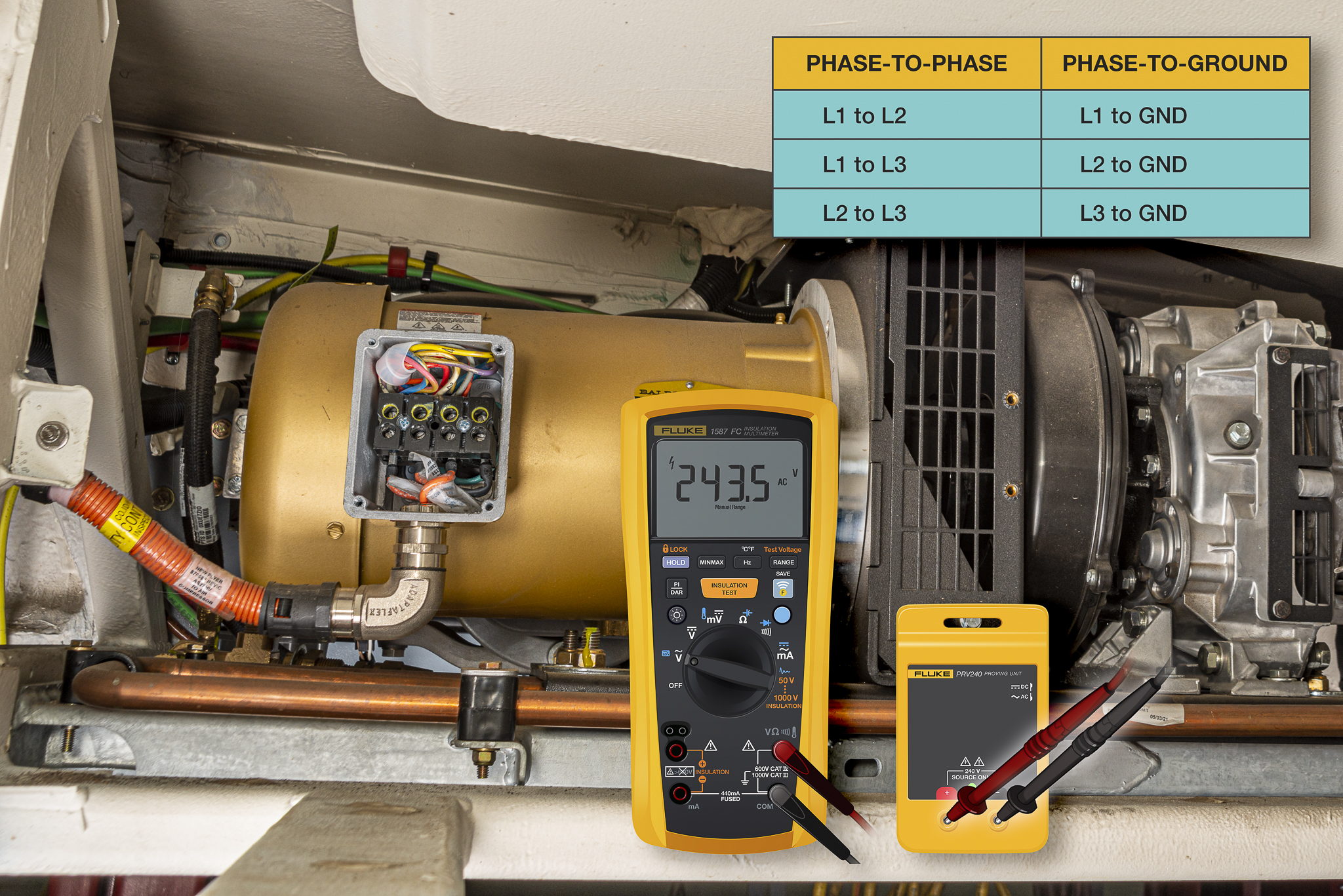
Step 2: Using a Fluke Proving Unit, test the DVOM to ensure it is working correctly. Set both your DVOM and Proving Unit to measure AC Volts.
WARNING: Verify zero or near zero voltage for each phase-to-phase measurement. Meter may read dissipating capacitance before reading zero volts or near zero volts.
Step 3: Measure from L1 to L2; L1 to L3; and L2 to L3.
WARNING: Verify zero or near zero voltage for each phase-to-ground measurement.
Step 4: Measure from L1 to GND; L2 to GND; and L3 to GND.
Step 5: Using the Fluke Proving Unit, test the DVOM again to ensure it is still working correctly.
Following confirmation of zero voltage, you and other maintenance personnel can begin inspection, service or repair on the bus, if:
All LOTO and ZVV procedures were followed and successfully completed
It is certain that the high voltage system and any high voltage component(s) to be serviced have been placed into an electrically safe work condition
VOLTAGE
The meter measures voltage with two probes. Remember that each probe is separate and the DVOM readout shows the difference between the probes. For example, if you check the voltage of the battery, the red probe touches the B+ (positive) terminal and the black touches the B- (negative) terminal. Since the red probe has 12 volts and the black probe has 0 volts, the DVOM reads 12 volts. This concept is important to understand to be able to use a meter efficiently.
Note: DIN standard wiring diagrams use terminal designators 30 for Battery + and 31 for ground.
How to check for voltage:
The black test lead is connected to ground (B-, negative) during the entire test.
The red test lead will measure voltage throughout the circuit. This measurement indicates how much voltage is available at each point.
Remember, all voltage is potential. Voltage can be lost, or dropped anywhere in the circuit due to looseness, corrosion and damage.
To measure voltage:
Select the DC voltage position on the DVOM.
Plug the black test probe into the COM input terminal jack. Plug the red test probe into the volts (or VDC) terminal jack.
Set the meter to the Auto ranging setting or the highest range to prevent damage to the meter.
Touch the probes across the circuit being tested and take the reading.
View the reading, being sure to note the unit of measurement.
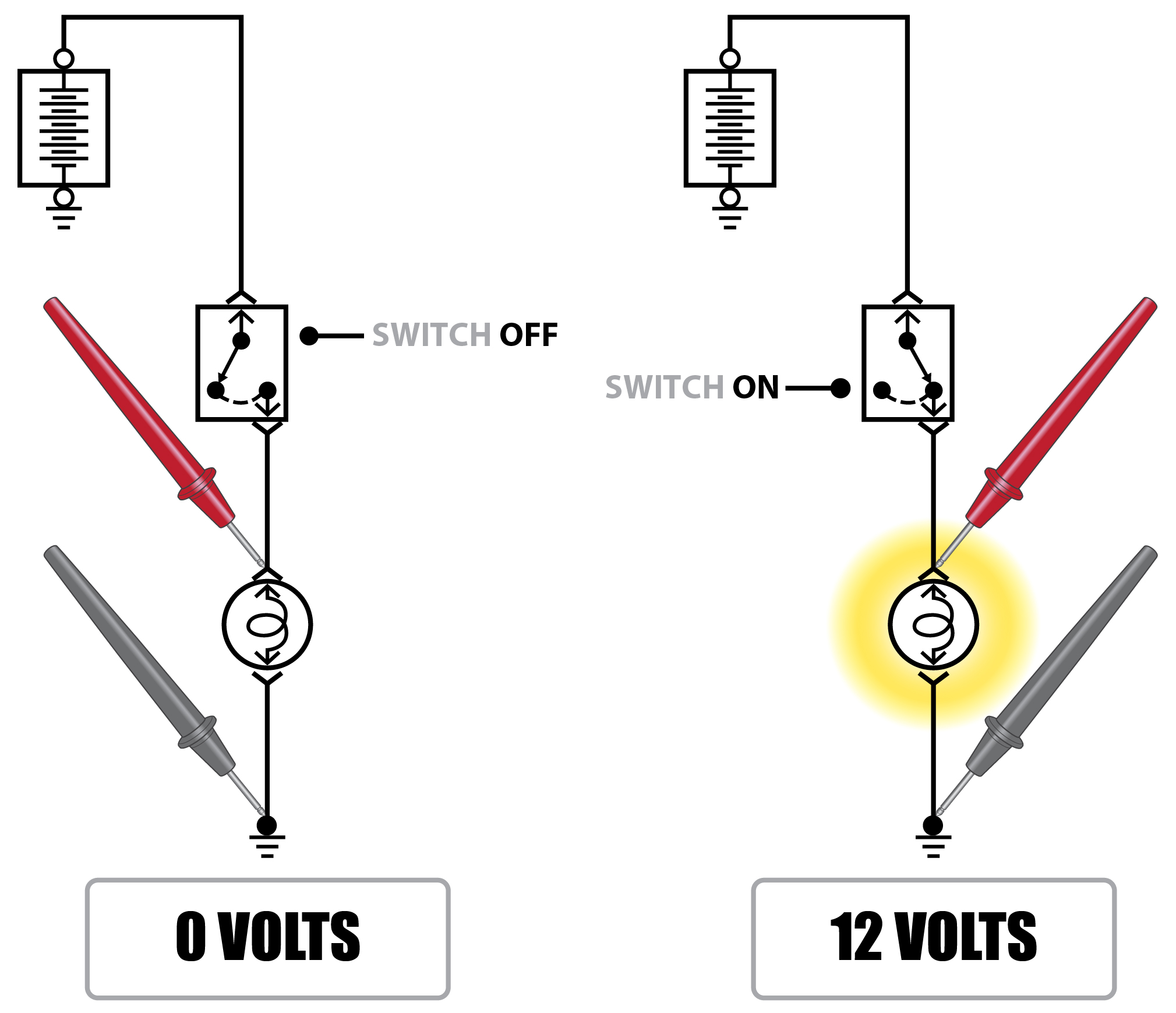
Example:
If measuring a simple circuit with a single lamp, you would place the red probe on the positive side of the lamp circuit and the black probe on the negative side of circuit. With the circuit switched off, you should have a reading of 0 volts. Once you activate the circuit, the reading should change to 12 volts and the lamp should illuminate. If the bulb does not illuminate, and you still have a reading of 12 volts, you have verified that the electrical circuit is good and that the light bulb itself had failed.
When to use:
Voltage checks are the most common electrical tests. Here are a few examples of when voltage measurements should be used:
Testing for proper supply voltage.
Testing basic wiring integrity.
Diagnosing for open and shorted circuits.
Voltage Drop:
Voltage drop is the most important test a technician can do when testing a circuit. When it has been identified that the circuit has a problem and the diagnostic process has begun, a voltage drop test will be your best diagnostic weapon to find the problem quickly.
How to test for voltage drop:
The circuit must be in an active state.
The meter is set up the same as for a normal voltage reading.
The meter is going to measure the difference in voltage between probes. You must understand the circuit you are testing prior to making measurements.
It is going to measure the various voltage drops and allow you to divide the system for easier diagnosis.
SAE Recommended Maximum Voltage Drops
Component
Voltage Drop
Small current connections
0.0V
Large current connections (fuel pumps, headlights etc.)
0.1V
Ground connections
0.1V
High current cables (battery/starter cable)
0.3V
Switch or relay contacts
0.3V
Note: All measurements should be made at normal operating voltage and load. Individual voltage drops are cumulative in a circuit.
Common symptoms of unwanted voltage drop:
Inoperative electrical parts.
Sluggish, lazy electrical devices.
Erratic, intermittent devices.
Devices that work sluggishly or erratically during periods of high electrical loads.
Excessive radio interference or noises in the radio.
Engine or transmission performance complaints.
No-starts or hard starts.
Improper sensor or computer voltages.
Erratic engine or transmission computer performance.
Faults in onboard computer system circuits.
Things to remember:
Visual inspections miss most cases of electrical voltage drop. You usually can't see the corrosion inside a connection or the damaged wire that is causing the problem.
Ground-side voltage drop, a commonly overlooked source of electrical trouble, can cause many of these symptoms. Any circuit or component is only as good as its ground.
The more sophisticated electrical systems become, the more important grounds are. The number of electrical components has increased rapidly and most do not have separate ground wires. Instead, these devices are grounded to the engine or body. Rust, grease, vibration and/or careless repairs can cause unwanted resistance resulting in a voltage drop from the engine/body back to the battery.
Many components such as engine sensors share a common ground. Therefore, a bad ground may complicate diagnosis because it could affect several components at once.
Some shop manuals and diagnostic charts or fault trees recommend checking grounds last. In reality, it is much quicker to check ground circuits before you follow the fault tree.
It's quicker and smarter to routinely check a circuit's voltage drop than it is to memorize long lists of symptoms. If experience has taught us nothing else, it's that chasing symptoms is no substitute for routine and thorough voltage drop testing.
Example:
Using the same example from the voltage measurement above, the technicians first check verifies that 12 volts is applied to the circuit at point A at the battery positive terminal. The technician then measures 12 volts available at point B going in to the switch. The red test lead is then moved to point C and 9.8 volts is measured out of the switch. At point D the technician measures 9.8 volts on the positive side of the bulb. There is a voltage drop of 2.2 volts across the switch. A normal switch or relay would only drop 0.3V. This indicates that we are "dropping" some voltage inside the switch and the switch has been verified to be faulty.
CURRENT
Current measurements are different from other DVOM measurements. Current measurements require connecting the meter in series with the circuit being measured. This way, all of the circuit current flows through the DVOM's circuitry.
How to make current measurements:
Turn off power to the circuit.
Select current (or Amps) on the meter.
Plug the black test probe into the COM input terminal jack. Plug the red test probe into the amp or milliamp input terminal jack, depending on the expected amperage measurement. It is a good idea to start with the highest amperage scale in order to prevent blowing the fuse inside of the meter.
Connect the probe tips to the circuit across the break so that all current will flow through the DVOM (a series connection).
Turn the circuit power back on.
View the reading, being sure to note the unit of measurement.
Always be aware of what current you expect. If the meter is only rated to 10 amps, you can easily blow the fuse or damage the meter.
When to measure current:
Use when checking parasitic draw on the vehicle.
Control module output to various sensors and relays.
Can only be used on low load items. Never measure high current items with DVOM test leads.
Example:
A vehicle with a low battery is being diagnosed for a parasitic drain in the electrical system. The test leads are installed in the correct input terminals and the DVOM rotary switch is set to read amperage. The negative test lead is placed on the battery negative cable clamp and the positive test lead to the battery negative post. While slowly removing the negative battery clamp the meter displays 4.2 amps. The technician has just verified that there is a large current draw in the electrical system. Additional pinpoint testing will be required.
RESISTANCE
Resistance is measured in ohms, indicated by the Ω symbol. It requires a thorough understanding of the item being tested.
Issues with resistance checks in vehicles:
Requires the technician understand the correct resistance value of the component being tested, i.e. the repair manual says a relay solenoid should read 65 ohms.
Requires the circuit be in the off position with no electricity flowing.
How to test for resistance:
Turn off power to the circuit.
Select resistance (or Ohms) on the meter.
Plug the black test probe into the COM input terminal jack. Plug the red test probe into the Resistance or Ohms terminal jack.
Connect the probes across the component or portion of the circuit for which you want to determine resistance.
View the reading, being sure to note the unit of measurement.
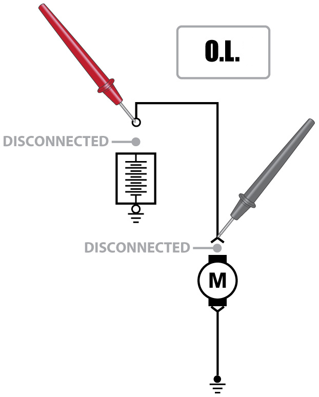
Example:
While testing a motor that is inoperative, the technician finds that there is no voltage available to the motor. The battery positive cable is disconnected and the rotary switch on the DVOM is set to measure resistance. The red test lead is placed on the disconnected positive wire. The black test lead is placed at the wire leading to the motor. The meter display reads O.L. The technician has verified the wire is open.
Change meter to see calcuations.
Change meter to see calcuations.
Select each DVOM function/feature to learn more.
Be sure to view the About section to explore all the ways to unleash and unlock the power of DVOM+.